Thursday, November 28, 2013

Online Tool for Easily Write Inline Assembler from Arduino IDE

Inline assembler is practical optimizing technique to speed-up some time-sensitive routines in your program. Unfortunately, it's not as convenience as it should be, for example:
  • You have to enclose asm instructions within quotes
  • You have to manually add hard-coded line separator (and tabs, for making it readable for later debugging)
  • You have to manually describe what register used for input/output, plus you have to report what registers are being clobbered
To help you assembler-inlining, we create this simple tool for you. No software to download / install, it's running right in this blog using embedded javascript. Just type your code below and hit the  Generate Code  button below, an inline assembler code suitable for avr-gcc will be automatically generated.
Enter your plain assembler code below...
Click to generate inline assembler code...

Make Your Arduino Uno Runs 25% Faster

Your Arduino Uno comes with 16 MHz crystal, thus it runs at nearly 16 MIPS (since most of instructions are executed in single cycle). As you might know, Arduino Uno utilize ATmega328 MCU from Atmel. One obvious fact that strangely most of ordinary Arduino users don't know is that the MCU's top speed is actually rated at 20 MHz, not 16 MHz! 16 MHz is official speed limit of MCU used in early version of Arduino, ATmega8 (up to Arduino NG and Severino). Carried on with this obsolete limit, Arduino Uno is still clocked with 16 MHz crystal.

To boost your Arduino Uno's performance up to 25% faster, all you have to do is replace the 16 MHz crystal with 20 MHz crystal, and update the bootloader with one that designed for this upgraded speed (see instruction below).

Please note that this is NOT overclocking, we'll just tuning it to maximum speed allowed by manufacturer as stated in ATmega328 datasheet. So it's 100% safe and guaranteed to run as reliable as before, it's just 25% faster :) up to nearly 20 MIPS!

Step 1: Add following content to your boards.txt (located in hardware/arduino sub-directory of the Arduino application directory, i.e. \Program Files (x86)\Arduino\hardware\arduino in default installation path on 64-bit Windows (or \Program Files\Arduino\hardware\arduino if you're still using the immortal WinXP ;)...

##############################################################

atmega328_20.name=Arduino Uno++ 20MHz

atmega328_20.upload.protocol=stk500
atmega328_20.upload.maximum_size=30720
atmega328_20.upload.speed=57600

atmega328_20.bootloader.low_fuses=0xFF
atmega328_20.bootloader.high_fuses=0xDA
atmega328_20.bootloader.extended_fuses=0x05
atmega328_20.bootloader.path=atmega
atmega328_20.bootloader.file=ATmega328_20MHz.hex
atmega328_20.bootloader.unlock_bits=0x3F
atmega328_20.bootloader.lock_bits=0x0F

atmega328_20.build.mcu=atmega328p
atmega328_20.build.f_cpu=20000000L
atmega328_20.build.core=arduino
Step 2: Create new file with name ATmega328_20MHz.hex under hardware/arduino/bootloaders/atmega sub-directory with following content:
Step 3: desolder the old 16 Mhz crystal from Arduino Uno board. Please note that this action may void your warranty, please proceed on your own risk! If you're unsure with this, perhaps it's better to build a brand new Arduino compatible board by your own from scratch. For example, you can buy Playduino-One kit from Play-Zone — they ship worldwide — for Fr. 19.9 (about USD 21). If you live in Indonesia, you can also purchase Playduino-One Kit from azTech for only Rp150.000,- (less than USD 14).
Step 4: Install a 20 MHz crystal. Soldering should be easy since space on bottom surface is sparse.
Step 5: Burn the bootloader: open Arduino IDE, if you've done step #1 correctly then a new board should be appear under Tools > Board menu with name Arduino Uno++ 20MHz. Select the new board, attach USB cable to Arduino (or ISP programmer if you build Playduino One), and execute Tools > Burn Bootloader command. That's all, now you have a much faster Arduino!

Sunday, November 24, 2013

Virtual USB port for AVR Microcontrollers

V-USB (formerly known as AVR-USB) is a software-only implementation of a low-speed USB device for Atmel’s AVR® microcontrollers, making it possible to build USB hardware with almost any AVR® microcontroller, not requiring any additional chip.

V-USB can be licensed freely under the GNU General Public License or alternatively under a commercial license. A comprehensive set of example projects demonstrates the wide range of possible applications.

Features of V-USB:
  • Fully USB 1.1 compliant low-speed device, except handling of communication errors and electrical specifications.
  • Example projects demonstrate device and host driver implementations on Linux, Mac OS X and Windows.
  • Supports multiple endpoints: one control endpoint, two interrupt/bulk-in endpoints and up to 7 interrupt/bulk-out endpoints. (Note that the USB specification forbids bulk endpoints for low speed devices, but V-USB supports them to some degree.)
  • Transfer sizes up to 254 bytes by default, more as configuration option.
  • Comes with freely usable USB identifiers (Vendor-ID and Product-ID pairs).
  • Runs on any AVR microcontroller with at least 2 kB of Flash memory, 128 bytes RAM and a clock rate of at least 12 MHz.
  • No UART, timer, input capture unit or other special hardware is required (except one edge triggered interrupt).
  • Can be clocked with 12 MHz, 15 MHz, 16 MHz or 20 MHz crystal or from a 12.8 MHz or 16.5 MHz internal RC oscillator.
  • High level functionality is written in C and is well commented.
  • Only about 1150 to 1400 bytes code size.
  • Choice of licensing type: Open Source or commercial.
This diagram shows a typical circuit for a bus powered device using Atmel ATtiny2313 MCU...
D1 and D2 are a low cost replacement for a low drop 3.3 V regulator chip, such as the LE33. Operating the AVR at higher voltages exceeds the common mode range of many USB chips. If you need to run the AVR at 5 V, add 3.6 V zener diodes at D+ and D- to limit the voltage.
Download the V-USB package containing a short description and several simple code examples.

Tuesday, November 12, 2013

Arduino UNO USART

Arduino Uno utilizing ATmega328P for it's main controller. Usually we use Hardware Serial library provided by Arduino. It's great library, except for three factors:
  1. It can NOT achieve highest speed actually possible by hardware UART underlying in it's core processor due to overhead in it's library implementation
  2. It's bloated in size, consuming a lot of unoptimized code
  3. It's hide powerful options which can be actually utilized to maximize performance
These conditions are actually derived from necessity (for Arduino broad range of user level) because Arduino library were intended to transparently support broad range of MCUs (resulting in unoptimized code) and to cover unexperienced programmer by rechecking every possible conditions which may lead to program malfunction. Take example the digitalRead example which checks PWM state every time it's being invoked.

Now, since we're trying to boost up Arduino to it's maximum potential, we need to understand the background process, sometimes in it's lowest level. Once we understand them, we can write efficient code which execute faster and consuming less resource than those consumed by the standard library.

The most source of information is certainly from Atmel's own-released datasheet. If you haven't had one, take a time to download it: [ ATmega328P Datasheet Complete Edition ]

USART is described in detail on it's own section, please refer to page 127-156 on the datasheet. For your convenience, some parts are copy-pasted on this article (marked with yellowish background).

USART Features on ATmega328

The Universal Synchronous and Asynchronous serial Receiver and Transmitter (USART) is a highly-flexible serial communication device. The main features are:
  • Full Duplex Operation (Independent Serial Receiveand Transmit Registers)
  • Asynchronous or Synchronous Operation
  • Master or Slave Clocked Synchronous Operation
  • High Resolution Baud Rate Generator
  • Supports Serial Frames with 5, 6, 7, 8, or 9 Databits and 1 or 2 Stop Bits
  • Odd or Even Parity Generation and Parity Check Supported by Hardware
  • Data OverRun Detection
  • Framing Error Detection
  • Noise Filtering Includes False Start Bit Detection and Digital Low Pass Filter
  • Three Separate Interrupts on TX Complete, TX Data Register Empty and RX Complete
  • Multi-processor Communication Mode
  • Double Speed Asynchronous Communication Mode

A simplified block diagram of the USART Transmitter is shown in following figure. CPU accessible I/O
Registers are shown with green boxes, and I/O pins are shown in blue boxes. The USART Data Register UDR is shown in yellow boxes. Please note that altough shown as two boxes in diagram below, there is only one UDR register which functioned as register for holding either received byte  / byte to be transmitted.

ATmega328 USART Block Diagram

On diagram above, you'll notice on the top block is Clock Generator section. This section conduct the whole orchestra of USART operations. It generates the base clock for the Transmitter and Receiver.

There are four modes of clock operations:
  • Normal Asynchronous mode
  • Double Speed Asynchronous mode
  • Master Synchronous mode
  • Slave Synchronous mode
To select Asynchronous mode, clear UMSEL bit in UCSRC (USART Control and Status Register C). In other hand, set UMSEL bit to select Synchronous mode.

To activate Double Speed Asynchronous mode, after clearing the UMSEL bit (to set USART into Async mode), set the U2X bit of UCSRA register. Clearing the U2X bit bring back USART to normal Async mode. For synchronous mode, this bit has no effect and should be cleared.

For Synchronous mode (UMSEL=1), data is clocked in sync with XCK pin (PD.4, pin#6 of ATmega328). In this case, value of DDR_XCK (Data Direction Register for XCK Pin) determine whether the clock source is internal (Master mode, MCU is the one who generate clock signal into XCK pin) or external (Slave mode, MCU is following clock signaled on XCK  pin from other party). The XCK  in is only active when using Synchronous mode. Please note that while in Sync mode, since PD.4  is shared the same physical pin as XCK  (pin#6), it's no longer functioned as General I/O pin.

Except for Synchronous Slave Mode, all other modes requires the MCU to generate clock signal. This is done internally by Clock Generator section (refer back to block diagram above).

As shown in the diagram, register related to this section is UBRR, acronym for USART Bit Rate Register. It's actually a 12-bit register, thus it's divided into two byte: UBRRH register for the high-byte (note that only lower nibble of this register is being used) and UBRRL register for the low-byte.

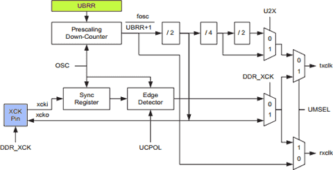
Following is detailed block diagram of Clock Generator section:

USART Clock Generator Block Diagram

The UBRR and the down-counter connected to it function as a programmable prescaler or baud rate generator. The down-counter, running at system clock (fosc), is loaded with the UBRR value each time the counter has counted down to zero or when the lower byte (UBRRL) Register is written. A clock is generated each time the counter reaches zero. This clock is the baud rate generator clock output, equal to  fosc / (UBRR+1).

The Transmitter divides the baud rate generator clock output by 2, 8, or 16 depending on mode being selected. The baud rate generator output is used directly by the Receiver's clock and data recovery units. However, the recovery units use a state machine that uses 2, 8, or 16 states depending on mode set by the state of the UMSEL, U2X and DDR_XCK bits (examine flow logic shown by arrow lines on the diagram).

Following table constains equations for calculating the baud rate (in bits per second) and for calculating the UBRR value for each mode of operation using an internally generated clock source:


BAUD = Baud rate (in bits per second, bps)
fosc = System Oscillator clock frequency
UBRR = Contents of UBRRH and UBRRL Registers (12 bits, 0-4095)

Thus for fosc = 16 MHz (frequency of oscillator used in Arduino Uno), we can calculate the value of UBRR on Async Double Speed Mode (U2X=1) by formula:
UBRR= ( 16,000,000 / 8*BAUD ) - 1
 = (  2,000,000 /   BAUD ) - 1
According to this equation, following is the value for common baud rates (Error Margin on the third row is rounding error caused by rounding a float number into it's corresponding integer value):

Baud Rate24004800960014.4K19.2K28.8K38.4K57.6K115.2K250K
UBBR Value832416207138103685134167
Error Margin-0.1%0.2%-0.1%0.2%-0.6%0.2%-0.8%2.1%

Note that in Double Speed mode, although for Transmitter it has no down-effect, the Receiver will only use half the number of samples (reduced from 16 to 8) for data sampling and clock recovery (it's the cost we paid for doubling the speed). Thus in this mode a more accurate baud rate setting and system clock are required. Avoid using baud rate with high error margin (such 28.8K, 57.6K, and especially 115.2K with 2.1% error margin). If you need to use 115.2K, better use Normal Async mode (with double speed turned off, U2X=0) and set UBRR value to 8 (although it's error margin will be increased to -3.5%, but with double sample the USART can compensate better and less prone from error).

[ to be continued ]